Coordinate references
The project database contains two Coordinate references configuration objects: one for Plant Modeller and one for Piping Isometrics & Spools. In these configuration objects, the administrator can define reference planes in X, Y and Z direction, which then allows the designers to refer to coordinate values and positive/negative directions by using symbolic names. How these named coordinates can be used is application specific:
-
In Plant Modeller, named coordinates can be used, for example, as navigation input or to indicate location. For example, a user can navigate 200 mm eastward from LINE1 by entering "LINE1 E 200" (or simply "LINE1 + 200", if east is the positive direction) or press the comma key "," to display the current cursor location in a user-friendly way. Also, the entire grid of reference planes can be shown in Plant Modeller work views.
-
In Piping Isometrics & Spools, named coordinates are only used in labels.
Defining reference planes
You can define reference planes separately for Plant Modeller and Piping Isometrics & Spools. If the same reference planes are suitable for both, you can define the settings for one application and then copy them to the other.
Do the following:
-
To define reference planes for Plant Modeller, do one of the following:
-
In Plant Modeller, select File > Environment > Coordinate references.
-
In the Project Environment dialog, browse to [project] > Configuration > Plant Modeller and double-click Coordinate references.
To define reference planes for Piping Isometrics & Spools, do one of the following:
-
In Piping Isometrics & Spools settings, select Project Administrator's Tools > Coordinate References > Create or Modify Coordinate References.
-
In the Project Environment dialog, browse to [project] > Configuration > Isometric Drawings and double-click Coordinate references.
The Edit Coordinate References Grid dialog opens.
-
-
Load template allows you to replace the current settings by loading another coordinate references object from the project database.
Important: This overwrites the configuration you are currently editing. Normally, you would only use Load template when you have created coordinate reference settings for one application and then want to copy the same settings to the other application.
-
Reference grid description displays the name of the coordinate references object. The name cannot contain the semicolon character.
-
Select whether to define reference planes in X, Y or Z direction by clicking the respective tab. The selected tab displays a list of reference planes that is arranged according to the coordinate values (not by name).
-
Define the general settings:
-
Coordinate conversion code – Select which of the One-character format codes to use for formatting numeric values in these reference planes. For example, code "a" (a 334) means the metric system without decimals.
-
Negative direction name – Type the name to use for indicating the negative direction of the plane.
-
Positive direction name – Type the name to use for indicating the positive direction of the plane.
-
-
To add one new reference plane, click Add and define the settings described in Add/Edit Coordinate Reference Plane.
-
To add multiple reference planes, click Add multiple and define the settings described in Add Multiple Reference Planes.
-
To modify a reference plane, select the reference plane and click Modify.
-
To delete a reference plane, select the reference plane and click Delete.
-
When you have defined the required reference planes in X, Y and Z direction, click OK.

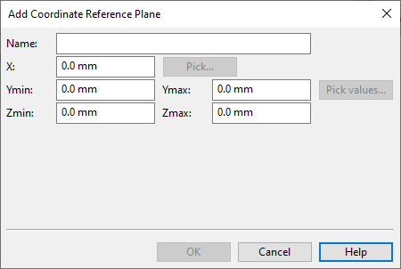
Add/Edit Coordinate Reference Plane
In the Edit Coordinate References Grid dialog, the Add and Edit buttons open the settings of a single reference plane.
-
Name – Specify the name of the plane.
-
The name cannot be one of the reserved names (see Reference plane names reserved for CADMATIC Hull) and it cannot contain semicolons or /* comments */.
-
A name that must be valid for mathematical expressions (including coordinate input) cannot start with a number and it cannot contain spaces, tabs, or the + - * / characters.
-
-
X, Y, Z – Specify the coordinate value of the plane.
You can use Pick when it is possible to use 3D pick to define the coordinate value. When editing a Z direction plane and Enable slanted plane is enabled, you are prompted to pick Z, Z2 and Z3.
Note: Defining this coordinate value but no min–max values creates an infinite reference plane.
-
Enable slanted plane – Select this to define Z2 (Xmax–Ymin) and Z3 (Xmax–Ymax) for a slanted plane in Z direction. If not selected, Z2 and Z3 are set to the same value as Z.
-
min–max – Minimum and maximum limits for the plane. These fields define the boundaries of rectangular reference planes. For example, if a reference plane in X direction has Ymax = 1000, then the plane is not referable when the Y coordinate of the cursor is more than 1000 mm.
You can use Pick values when it is possible to use 3D pick to define the limits.
Add Multiple Reference Planes
In the Edit Coordinate References Grid dialog, the Add multiple button opens the settings for generating multiple reference planes with different X/Y/Z coordinate values and same min–max values. The coordinate value for each plane is incremented by a fixed value. If an ID number is used as part of the plane name, then also the ID number is incremented by one for each new plane.
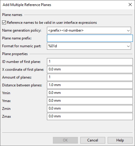
Plane names
-
Reference names to be valid in user interface expressions – Specify whether the plane name must be valid for use in mathematical expressions. If selected, the plane name cannot start with a number and it cannot contain spaces, tabs or the + - * / characters. Also, if the "-" character is part of the ID or the coordinate value, it is automatically replaced with the underscore character "_".
-
Name generation policy – Specify how to generate names for the planes.
-
<prefix><id-number> – Construct the names using a plane name prefix and a running ID number.
-
<prefix><coordinate value> – Construct the names using a plane name prefix and the plane's coordinate value. The name cannot be one of the reserved names (see Reference plane names reserved for CADMATIC Hull).
-
-
Plane name prefix – Specify the prefix string for generating the plane names. The prefix cannot contain semicolons. When Reference names to be valid… is enabled, the name has additional restrictions regarding valid characters, otherwise the only restriction is that the name cannot contain semicolons or /* comments */.
-
Format for numeric part – Specify the numbering format for generating the planes names with a prefix and an ID.
-
%01d – ID number has no leading zeros added.
-
%02d – ID number is at least two digits long (adds a leading zero, if needed).
-
%03d – ID number is at least three digits long (adds 1–2 leading zeros, if needed).
-
Plane properties
-
ID number of first plane – Specify the ID number of the first plane. For the second plane it is this value + 1, for the third plane it is this value + 2, and so on.
Note: If you want the first IDs to have leading zeros, make sure Format for numeric part allows them. For example, to create planes P01–P50, you can set the ID number of the first plane to either "1" or "01", but you must set the format to "%02d" or there will be no leading zero.
-
X/Y/Z coordinate of first plane – Specify the coordinate value for the first plane. For the second plane it is this value + Distance between planes, for the third plane it is this value + Distance between planes * 2, and so on.
-
Amount of planes – Specify the number of planes to be generated.
-
Distance between planes – Specify the distance to have between two consecutive planes.
-
min–max – Specify the minimum and maximum limits for the planes.
Coordinate references object's data structure
Coordinate references configuration objects are stored in COS in the following kind of structure:
title
x–header
x–planes
y–header
y–planes
z–header
z–planes
; is the standard DM field separator character
title: name of the coordinate system
Each X, Y, and Z header defines the following fields:
x_count; conv_code; pos_dir; neg_dir;
where
-
x_count is the number of reference planes that follow
-
conv_code is the conversion code
-
pos_dir is the name of the positive direction
-
neg_dir is the name of the negative direction
x-planes: list (any length) of definitions as:
ymin; ymax; zmin; zmax; x; name;
- The first five fields define a portion of a plane perpendicular to the X axis, and the last field specifies its name.
y-planes: list of definitions as
xmin; xmax; zmin; zmax; y; name;
- The usage of the fields is similar to that of the X plane.
z-planes: list of definitions as
xmin; xmax; ymin; ymax; z1; z2; z3; name;
- An arbitrary direction reference plane is defined by three points: (xmin, ymin, z1), (xmax, ymin, z2) and (xmax, ymax, z3).